

Description
Environment
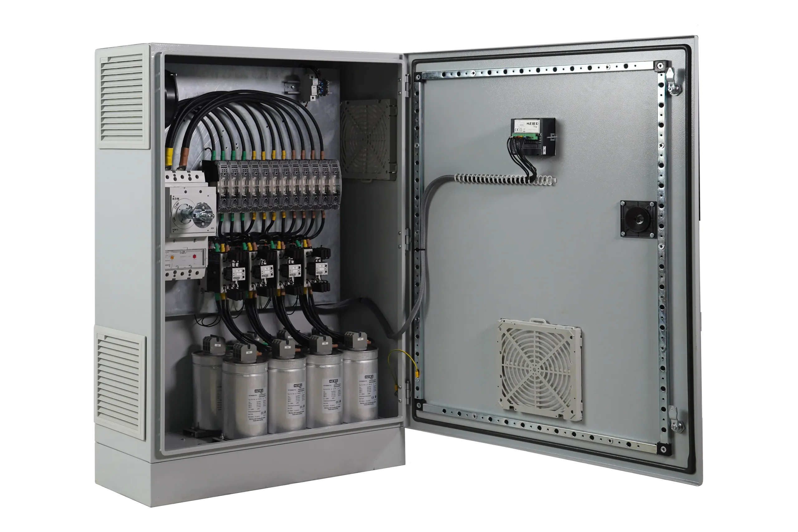
GENERAL CHARACTERISTICS
| Electrical Specifications | |
|---|---|
| Nominal voltage | 415 V – 50 Hz |
| Capacity Tolerance | -5%, +5% |
| Connection Type | Three-phase |
| Power Loss | < 2.5 W/kVAr |
| Maximum Allowable Current (with thermal protection included) |
1.43 In |
| Maximum Allowable Voltage | 1.1 x Un, 8h every 24h |
| Overload Protection | CHL Protection Alarm (Capacitor Harmonic Load) |
| Isolation Voltage | 690 V |
| Shock Withstand Voltage | 8 kV |
| Box | |
|---|---|
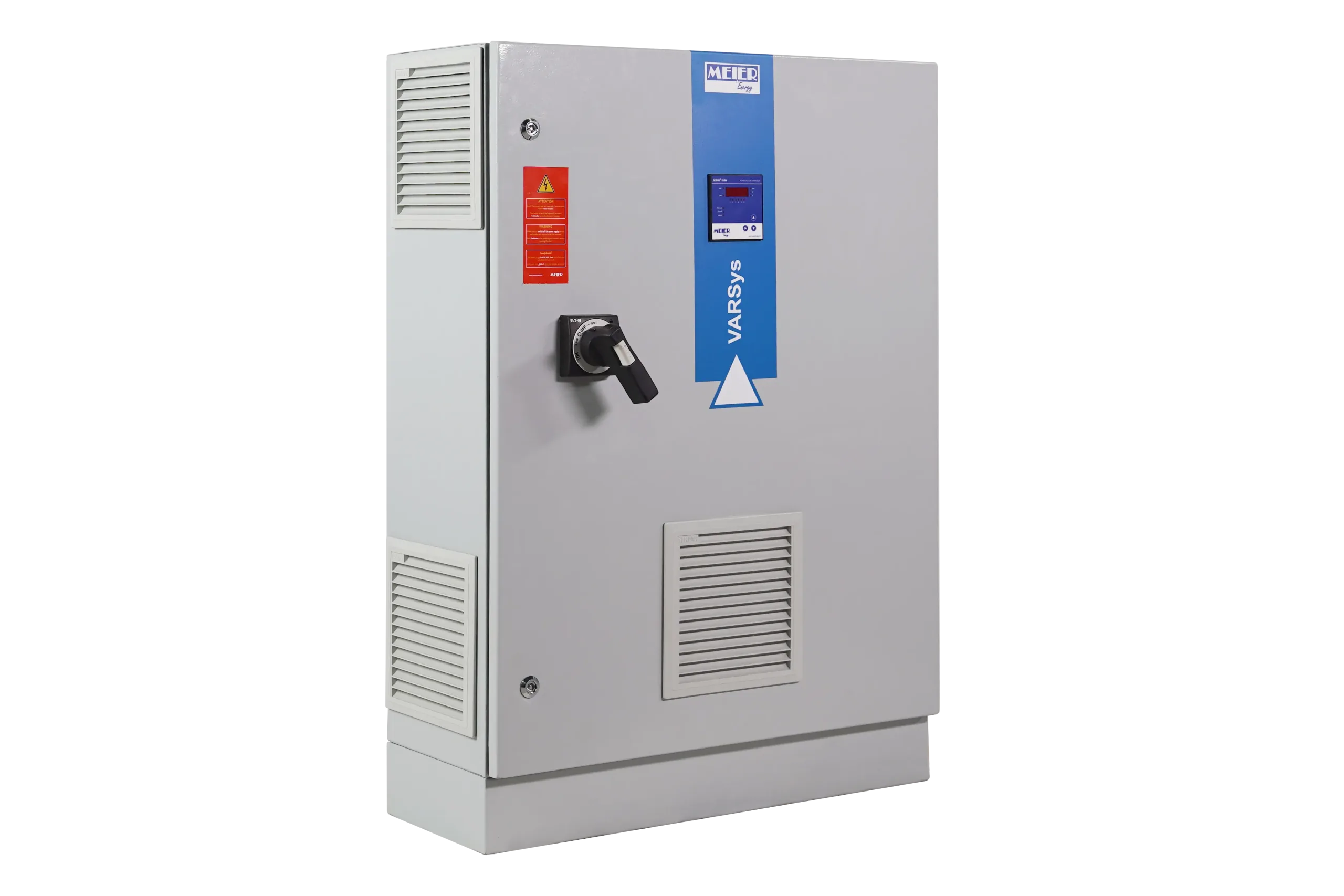
| Degree of protection | IP42 |
| Color | RAL 7035 |
| Degree of Mechanical Resistance | IK10 |
| Varmetric Relay | |
|---|---|
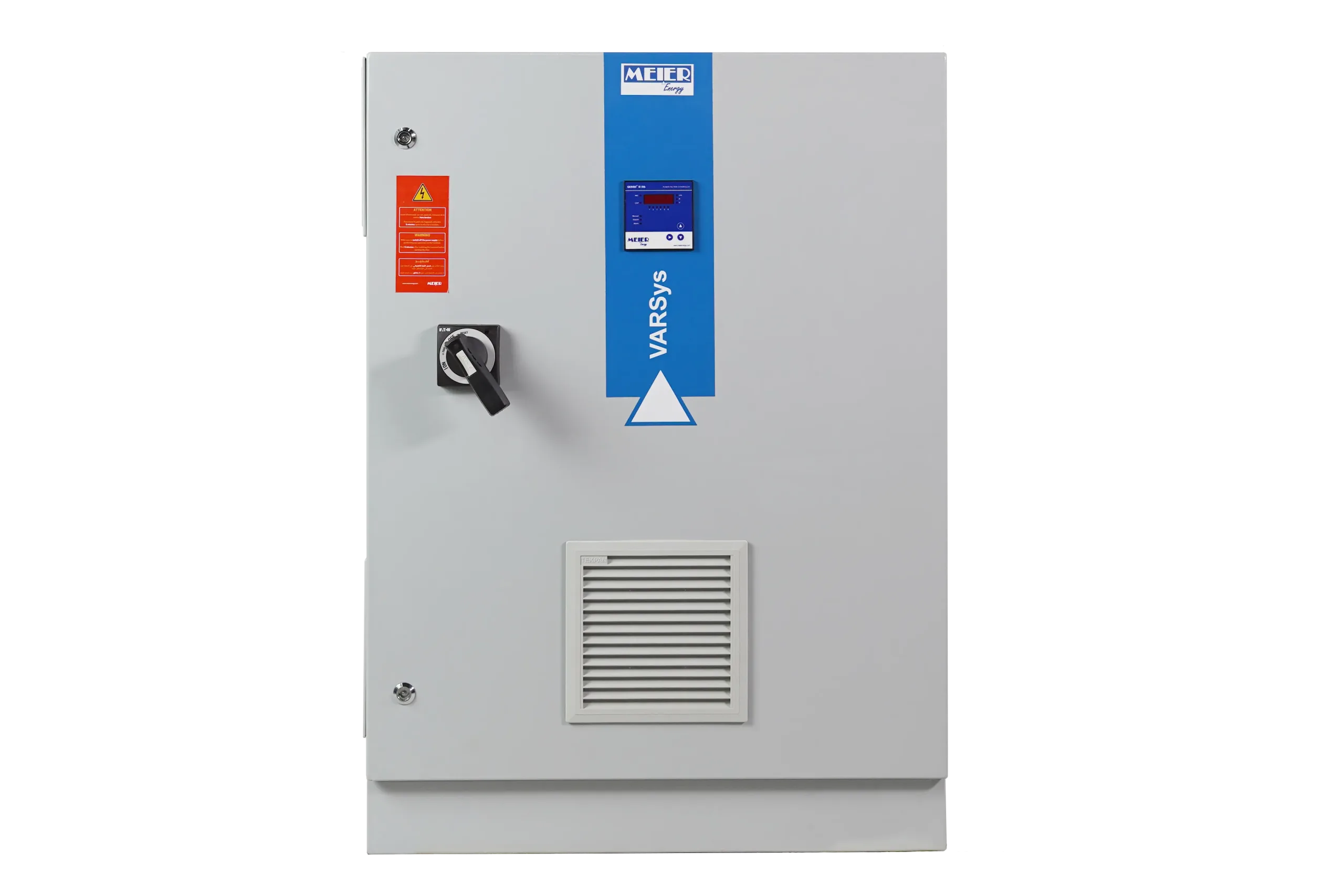
| Genius® | Genius® B106 (other options available) |
| Head Protection | |
|---|---|
| With Main Switch | Rotary Handle Switch-Disconnector The compensation bank must be protected upstream by a circuit breaker |
| With Circuit Breaker | Molded Case Circuit Breaker with Rotary Handle |
| Steps | |
|---|---|
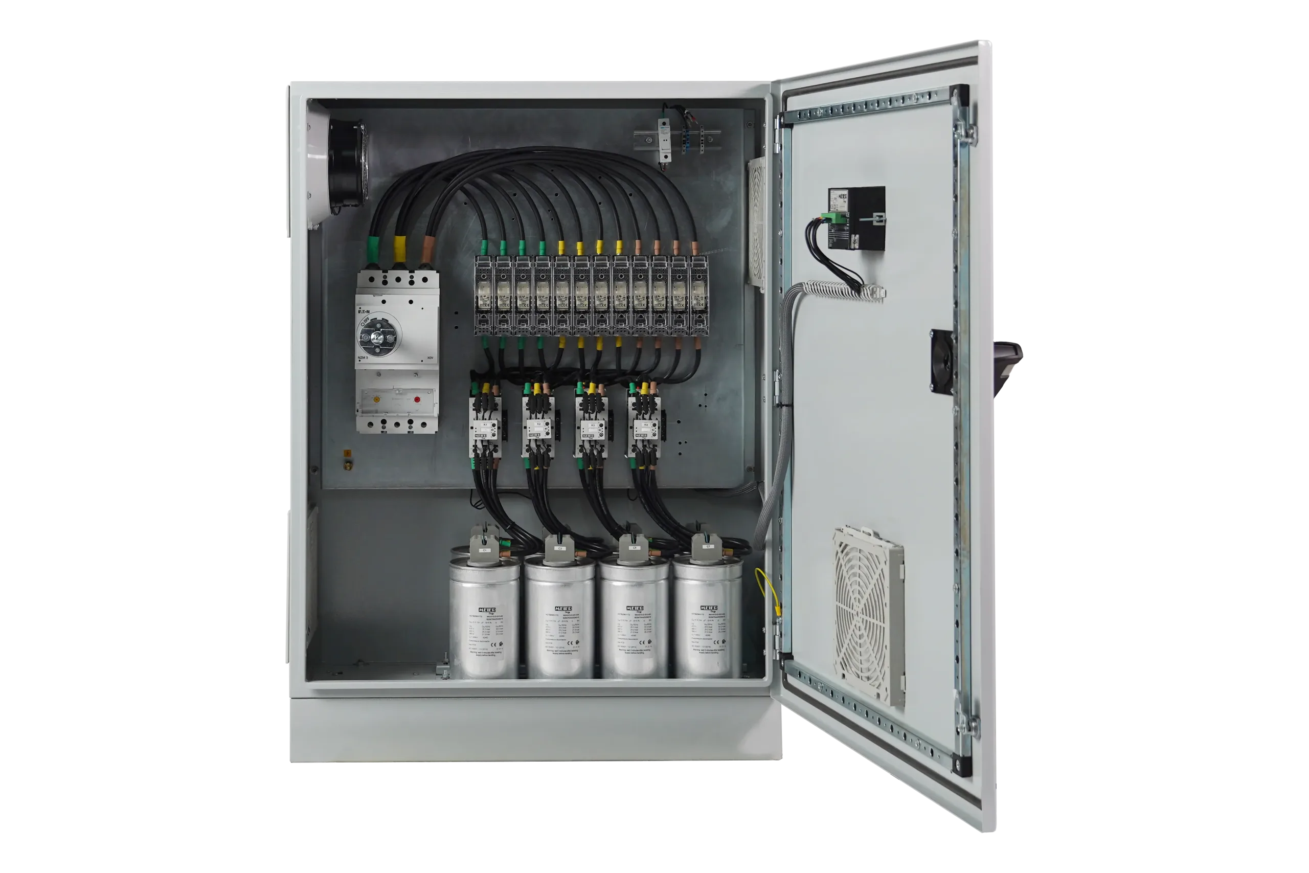
| Type of Capacitors | VARCap® 415 V – 50 Hz Maximum Overload: Up to 2.0 In Maximum Inrush Current: ≤500 In Operational Ambient Temperature: -40°C – +60°C Overvoltage Protection for all 3 Phases Discharge Resistance 50 V – 1 min |
| Contactors | KMC Range, dedicated to capacitor switching |
| Step protection | By gG-type fuse or by choice of Molded Case Circuit Breaker |
| Temperature Control | |
|---|---|
| Temperature Control | By Genius® controller |
| Communication | |
|---|---|
| ModBus | RS485 (optional) |
| Installation | |
|---|---|
| Auxiliary Power Supply | 230 V AC – 50Hz |
| CT (Not included) | >5 VA – secondary1 A or 5 A To be installed upstream of the load and the compensation bank |
| Emergency Group Contact | Input provided for the source changeover contact (optional) |
| Alarm Contact | Available for remote alarm reporting |
| Dimensions | |
|---|---|
| Power up to 200kVAR | Panel C4 – HxLxP : 1100 X 800 X 320 |
| Power up to 350kVAR | Panel C5 – HxLxP : 1200 X 900 X 420 |
Environment
GENERAL CHARACTERISTICS
| Electrical Specifications | |
|---|---|
| Nominal Voltage: | 415 V – 50 Hz |
| Capacity Tolerance: | -5%, +5% |
| Connection Type: | Three-phase |
| Power Loss | < 2.5 W/kVAr |
| Maximum Allowable Current (with thermal protection included) | 1.43 In |
| Maximum Allowable Voltage | 1.1 x Un, 8h every 24h |
| Overload Protection | CHL Protection Alarm (Capacitor Harmonic Load) |
| Isolation Voltage | 690 V |
| Shock Withstand Voltage | 8 kV |
| Box | |
|---|---|
| Degree of protection | IP42 |
| Color | RAL 7035 |
| Degree of Mechanical Resistance | IK10 |
| Varmetric Relay | |
|---|---|
| Genius® | Genius® B106 (other options available) |
| Head Protection | |
|---|---|
| With Main Switch | Rotary Handle Switch-Disconnector The compensation bank must be protected upstream by a circuit breaker |
| With Circuit Breaker | Molded Case Circuit Breaker with Rotary Handle |
| Steps | |
|---|---|
| Type of Capacitors | VARCap® 415 V – 50 Hz Maximum Overload: Up to 2.0 In Maximum Inrush Current: ≤500 In Operational Ambient Temperature: -40°C – +60°C Overvoltage Protection for all 3 Phases Discharge Resistance 50 V – 1 min |
| Contactors | KMC Range, dedicated to capacitor switching |
| Step Protection | By gG-type fuse or by choice of Molded Case Circuit Breaker |
| Temperature Control | |
|---|---|
| Temperature Control | By Genius® controller |
| Communication | |
|---|---|
| ModBus | RS485 (optional) |
| Installation | |
|---|---|
| Auxiliary Power Supply | 230 V AC – 50Hz |
| CT (Not included) | >5 VA – secondary1 A or 5 A To be installed upstream of the load and the compensation bank |
| Emergency Group Contact | Input provided for the source changeover contact (optional) |
| Alarm Contact | Available for remote alarm reporting |
| Dimensions | |
|---|---|
| Power up to 200kVAR | Panel C4 – HxLxP : 1100 X 800 X 320 |
| Power up to 350kVAR | Panel C5 – HxLxP : 1200 X 900 X 420 |